Introduction
MGG‘s micro-incandescent lamps represent a modern component for many fields in today’s electrical and electronics industries. The applications are so comprehensive and almost unlimited, that they cannot all be mentioned in detail here. Therefore we would like to give you detailed information about the technical aspects of lamps on the following pages; the materials used, individual processes and especially the definitions of the most important electrical and optical criteria.
Every lamp user must decide which characteristics are required from a light source he wishes to use. The most important parameters could be the following (not listed in order of importance):
|
|
|
|
|
|
|
|
|
|
|
Once the parameters have been decided, it is possible in many cases to select a lamp which is available “off-the-shelf“. This lamp can be to an international standard and therefore could be supplied easily world-wide.
Alternatively users sometimes specify parameters which cannot be fulfilled or which can be fulfilled only by the manufacturing of a customized lamp. This is the starting point for our development. We try to learn as much as possible about the application: operating data, ambient influences, mounting details, interchangeability etc.. With this knowledge we can find a solution which satisfies the criteria.
Naturally it is sometimes impossible to manufacture a lamp which conforms to every requirement. There are limits for incandescent lamps, based on purely physical considerations, or practical considerations to manufacturing techniques or cost constraints.
A comprehensive knowledge of micro-incandescent-lamps will surely allow the correct judgments to be made about the technical practicability concerned with your own requirements.
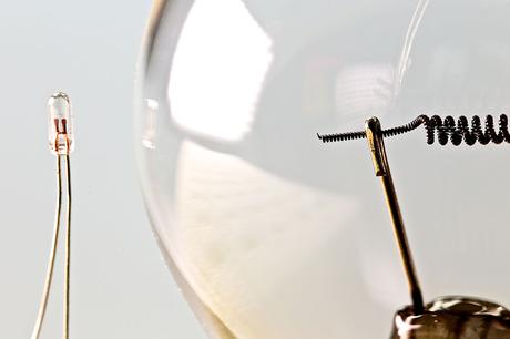
Filament
The ‘heart’ of every lamp is the filament. For MGG lamps the tungsten wire used in the manufacture conforms to highest quality requirements. Before manufacturing every wire is subjected to stringent quality control checks, to guarantee that only faultless wires are used. The smallest wire diameter in use is 2.9 micro meters, and this is mounted e.g. in the ‘smallest incandescent lamp in the world (dia. 0.75 x length 2.8mm). This lamp has a rating of 1.5V and consumes a current of 8mA only!
In order to produce the filament, the tungsten wire is uniformly spirally wound on a molybdenum core wire. The diameters of these wires, their grades and length of spiral, determine the electrical-, light- and mechanical- characteristics of the lamp in which the filament will be used.
Depending on the voltage for which the filament is designed, the first coil is sometimes spiraled itself again on a molybdenum core wire. This results in a coiled-coil filament which is available from 5V; it has a high mechanical strength and results in an almost point light source, being an important characteristic for e.g. lens-ended lamps.
After coiling the tungsten wire, the finished endless helix (the filament hose) is cut to the required lengths. The molybdenum core wire is dissolved by chemical etching, because it is no longer required. The filaments are finally subjected to a thorough cleaning process, in order to remove the last traces of etching fluid.
A small number of filaments are needed to make a sample batch of lamps, to determine whether the filaments confirm to the theoretical data. Only if this is the case, the filaments will be used for a production batch, so that MGG’s quality and reliability is maintained.
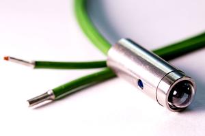
WIRE TERMINALS
Wire terminals (copper clad) are used as lead-ins in nearly every case (two per lamp). They consist of a nickel-iron alloy core which has a copper coating, guaranteeing a perfect vacuum seal between the glass beads and the glass bulbs. Other lead-in wires, e.g. platinum coated wires, can be used on request (for special lamps). The range of diameters of lead-in wires varies from 0.15 to 0.40mm. The most common lead-in wire size ranges from 0.20 to 0.25mm diameter.
SUPPORT WIRES
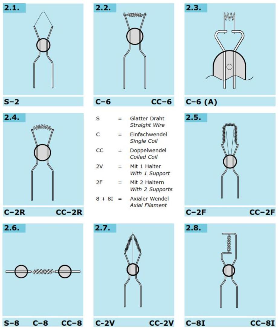
Some lamps require either one or two filament supports fused into the glass bead, to prevent the danger of filament collapse or contact with the inner wall of the glass bulb. These supports are made of molybdenum wire having a diameter of 0.10mm. Hooks are formed at their free ends to hold the filament. During manufacture the hooks are closed into eyes which totally enclose the filament so that it is held securely even under conditions of shock or vibration - see "filament constructions".
BEAD
The glass bead in a lamp answers several purposes. The bead melted round the wire terminal ensures constant electrode spacing and acts as a solid base for either one or two filament supports (please see filament illustrations). For T-1 ¾ lamps (with a diameter of 5.85mm) and smaller lamps the bead is simultaneously fused to the lead-in wire and the glass bulb.
BULB
For MGG-lamps four different kinds of bulbs are used:
- Round bulbs
- Flat bulbs
- Lens-ended bulbs
- Globular bulbs
The bulbs shown from item 1 to 3 are tubular and only differ in the method of closing the glass at the opposite end. Round bulbs are made hemispherical, flat bulbs are closed by a plane surface and lens-ended bulbs have a plano-convex lens (for sizes T-⅔, T-¾ and T-1). On projector and point-light lamps the lens is bi-convex. Globular bulbs are made uniformly spherical. All lamps are classified according to the shape of their glass bulbs. The designations result from Anglo-American literature:
- Lamps with tubular bulbs = tubes → T
- Lamps with globular bulbs = globes → G
Additional digits give details about the construction of the lamps, e.g. ‚T1‘ means a tubular lamp with a diameter of 3.175mm. ‘1’ stands for ⅛” (inch). Other lamp sizes are shown as multipliers for ‘⅛’ of an inch. Thus T-1¾ lamps have a diameter of 5.85mm. The lamps listed under ‘catalog’ are shown in T-groups with exception of indicator- and point-light-lamps. MGG glass bulbs are a blend of several sorts of glass, which combine with other materials in the best way.
The coefficients of expansion are carefully selected, to be compatible with the coefficients of expansion of the lead-in wires. Except the indicator-lamps T 1½ to T-1¾, all other bulbs - especially the lens-ended bulbs – are completely free of flaws, inclusions or impurities. In every case an undistorted light output from the lamp is guaranteed. At every stage of manufacture control checks are performed. The finished bulbs are subjected to statistical sampling before they are dispatched or subjected to assembly processes.
BASE
MGG-lamps are supplied with electro-tinned leads as standard, to ensure easy soldering (as per DIN40046 and MIL-T-10727). If required, we can supply gold-plated leads to MIL-G-45204. In addition to wire-ended versions, most of the lamps are available in a based form. Most of the bases used are to international standards, which enables easy replacement of lamps without soldering or the need for special tools. The sockets are shown in the catalogue.
COLOR- / SILICONE-CAPS
All glass bulbs are normally supplied in clear and transparent finish. If required, the following colors can be supplied: abrasion resistant, long-lasting, burnt-in lacquer color-coating ; or temperature resistant silicone-filter-caps:
|
|
|
|
|
|
|
|
The manufacturing process consists of two distinct ranges:
a) Component parts
b) Completed parts
Paragraph a) refers to the manufacture of filaments, the glass tubes and bulbs and the bases.
Paragraph b) refers to the normal lamp production.
The lead-in wires are fed automatically from reels, but to required length and fused with the bead to ensure a vacuum-tight seal. The filament which has already been manufactured is added automatically to the lead-in wires and is attached securely.
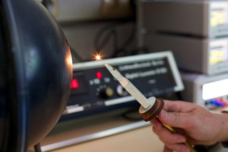
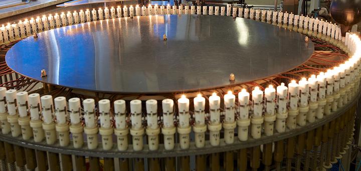
The completed wire and filament system passes on and is fitted with its glass bulb, which is then evacuated and sealed. The lamp then runs through the electro-tinning process, before it is subjected to burning-in (i.e. aging) on the burning-in racks. The burning-in time is fixed exactly for each type of lamp, the average being between 4 and 16 hours. Burning-in brings 3 advantages:
- Initial failures caused by poor manufacture or material can be detected and eliminated immediately.
- Filaments of the lamps are stabilized.
- Consistency of a manufacturing lot can be judged perfectly since a large number of lamps burns simultaneously.
After burning-in each and every lamp is measured and classified for its light and current consumption. Most of this testing is performed fully automatically in a processor controlled testing unit. Lamps which will be colored or which need further manufacturing processes, are dispatched for the next step. After basing or coloring random sample tests are made of mechanical and electrical characteristics. The completed lamps are stored, where they are immediately available for sale.
In order to maintain a constantly high quality level, it is necessary to maintain an active quality control and quality assurance system. This is independent of the production, but directly responsible to the management.
This control is divided into four areas:
- Goods incoming inspection of all materials
- Inspection of in-house manufactured components
- Statistical sampling of the manufacturing process
- Final inspection
Setting-up and running of all these controls have proved them to be most effective. We always detect and remove possible causes of defects before they are built-in in manufacture. Our own in-house work standards and technical specifications reflect feed-back from manufacturing very quickly.
Abt. 14% of all employees are engaged in quality issues. We take random samples from production for further examination and life testing. The knowledge obtained therefrom is used by the development and technical management to up-date the production and inspection procedures. This constitutes the basis for a steady high quality level and also pushes advancements in quality of our micro-incandescent lamps.
RATED VOLTAGE (U)
All operating voltages shown in the catalog are voltages at which all other parameters will be within specification, such as current input, candle power/luminous flux, resistance and life. This unit is called Volt (V).
RATED CURRENT (I)
The current which flows through the lamp at its rated voltage is called the rated current – in milliamperes (mA). Standard tolerance on the lamps listed in the catalog ± 10%. If required, close-tolerance or extended tolerance versions are available.
RATED POWER (P)
Product of rated voltage (in V) and rated current (in A) is the rated power input (W):
P = U x I ⇒ e.g. 28V x 0,040A = 1,12W
Standard tolerance is the same as the current input tolerance.
RATED RESISTANCE (R)
Unit of electrical resistance is Ohm (Ω). The rated resistance of a lamp is the quotient of rated voltage and rated current:
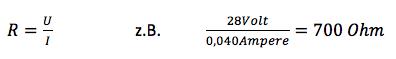
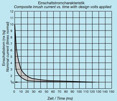
Incandescent lamps base on Ohm’s law. The tungsten wire used has a positive resistance coefficient. Resistance depends on voltage and temperature (PTC characteristic/resistor), i.e. resistance increases with rising temperature. So resistance of many lamps at room temperature (20°C = 293 K) is just 1/10 of normal operating temperature (ca. 2.000 K). Since inrush current is inversely proportional to the resistance, inrush current is approx. 10x of the steady-state current – see. Fig. 1.
Lamps with a low current rating (thin tungsten wires) do reach their operating temperature faster than lamps with a high current rating (thick tungsten wires).
Many electronic circuits resp. semiconductors could be damaged by high inrush current pulse. A reduction in inrush current can be achieved by constant ‘pre-heating’ of the filament by using between 10 – 15% of the operating voltage during the off-state. At a color temperature of about 1000K, there will be no visible light emission from the lamp.
GENERAL INFORMATION
The principle of operating incandescent lamps is based on the fact, that the electrical energy input is changed into visible radiation and thermal energy. Electromagnetic radiation that can be observed by the human eye is called ‘light’. The range of observable wave lengths varies from abt. 380 – 780 nm (nanometer), i.e. from violet to red. Although the visible radiation of an incandescent lamp just represents a small fraction of the input energy, lamps are effective emitters for many applications. The most important photometric units for MGG-lamps are the following:
LUMINOUS FLUX (ɸV)
The total radiation of a lamp/light source in the range of 380 to 78nm is called the luminous flux (lm).
LUMINOUS INTENSITY (IV)
Candela (cd) is the luminous intensity of a light source emitting a monochromatic radiation with a frequency of 540THz in a given direction in which the power radiation is 1/683 Wsr–1.
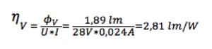
MEAN SPHERICAL CANDLE POWER (IOV)
Anglo-American literature knows the acronym MSCP. There is a direct relationship between candle power (MSCP) and total luminous flux (lm):
Φ∨ (lm) = 4π * lo∨ (MSCP) = 4π * MSCP = 12,57 * MSCP
e.g. MGG 1280-00 has .15MSCP = 1,89lm
For MGG lamps the mean spherical power is ±25%. Closer tolerance versions, e.g. ±15% (AS 15) and ±10% (AS 10), are available at extra cost. (The letters AS stand for aged and selected).
ILLUMINATION STRENGTH (EV)
The Illumination strength is called Lux (lx).
If a luminous flux of 1 lm illuminates a surface of 1m² vertically, the surface gets an illumination strength of 1 Lux (lx = lm/m²). Anglo-American literature knows the designation ‘foot candle’ (fc) instead of Lux (fc = cd/ft²)
1 fc = 10,764 lx 1 lx = 0,0929 fc.
Illumination strength is inversely proportional to the square of the distance of the illumination source. If two lamps give the same illumination strength on a surface, the candle power of the lamps is proportional to the squares of their distance from the surface.
LUMINANCE DENSITY (LV)
Luminance density is a measure of candle power projected onto a plane perpendicular to the radiation direction:
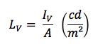
In simple terms, luminance density is the photometric measure that generally corresponds to the subjective perception of brightness of a light source (lamp).
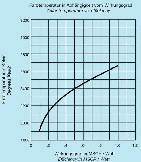
COLOR TEMPERATURE (TF)
Color temperature is scaled in Kelvin (K). Nearly all MGG-lamps are vacuum lamps. For projector lamps and some other special lamps, gas filled versions are manufactured. Vacuum lamps have a color temperature range from 1800 to 2600 K (up to a maximum of 10lm/W), gas filled lamps have color temperatures up to 2900K (max. 17 lm/W).
Incandescent lamps are thermal radiators in which the tungsten wire filament is heated by electric current flow to the temperature shown above. Among others, they emit visible light.
Candle power and luminous flux depend on the ‚absolute temperature` of the incandescent filament. Radiation of the filament corresponds very closely to that of a ‘black body’. The higher the filament temperature, the shorter the wavelength of the radiation, and the larger the proportion of visible light. This results in a higher luminous efficiency.
LIFE
The average life figures shown in the catalog are meant for alternating voltage (AC) operation under laboratory conditions, i.e. at room temperature, stabilized voltage, without any shock or vibration and in a vertical position. Life time of a lamp is said to have been reached when more than 50% of a sample batch under test are still illuminated.
MGG lamps are subjected to continuous life tests, i.e. random samples are taken from each production lot. Some lamps with particularly long lives (e.g. 100,000 hours = approx. 11.4 years) cannot be tested at their rated voltage. A shortened test at higher voltage is then performed.
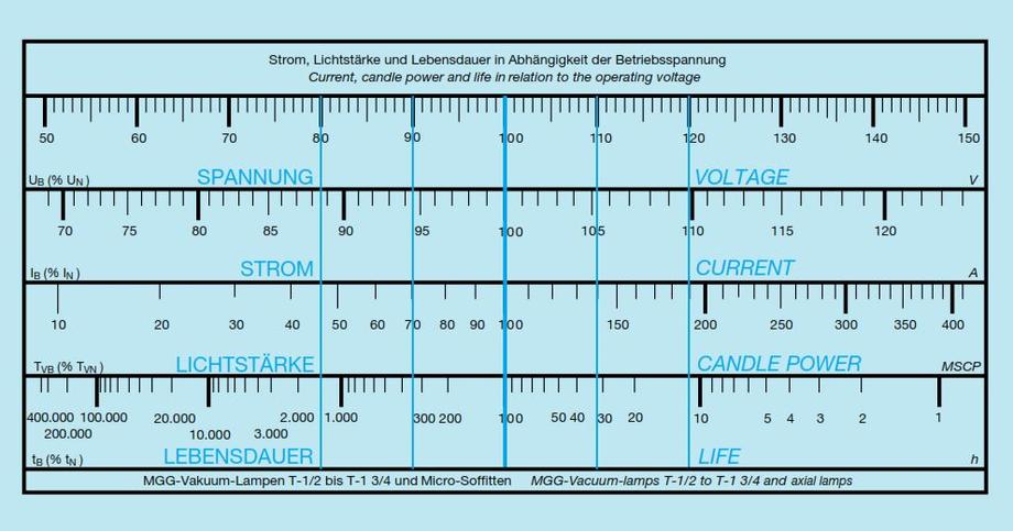
The results obtained from this test can be extrapolated to give rated life. A nomograph is shown in fig. 3. It is especially made for MGG lamps and is based on the knowledge obtained over a long period. It can be used, with some limitations, for nearly all vacuum lamps to correlate various parameters.
All data shown in the catalog, such as current, light output and life, are specified for rated voltage. However, in many cases there are special requirements demanding a different operating voltage for a lamp (e.g. in order to achieve a longer life time). Sometimes the application demands overrunning of the lamp. In all cases it is important for the user to know how other characteristics will change for a specified increase or decrease of operating voltage.
The MGG calculator shows the changes expressed as percentages, e.g.: For a 5V lamp operated on 4.5V (10% undervoltage). The vertical blue line passing through the 90% voltage mark shows (from its intersection of the other scales) that the current is reduced by abt. 5.5% to 94.5%, and the candle power by abt. 30% to 70% of the rated value. However, the intersection on life scale shows an increase of abt. 350% (3.5x).
As mentioned above, all life measurements are made under best conditions, so nearly every application leads to some reduction of the life attained. Some of the more important influences upon life are shown below:
EFFECTS OF MATERIAL USED IN MANUFACTURE AND TECHNOLOGY
Using perfect materials and assuring optimum conditions for manufacture and constant technical appraisal obtains a reliable product.
OPERATION MODE
The operation mode is an essential factor determining life of incandescent lamps. There are no problems associated with running lamps on alternating voltage (AC). However, direct voltage (DC) operation may result in life reduction to more than 50% - especially on lamps with a thin filament (low current) and low filament temperature. Adding the normal evaporation of the filament, other effects reduce its cross section:
- Soret effect
- Electromigration
The Soret effect is based on a considerable temperature gradient longitudinally along the direction of the wire axis. The occurring mass transport (of the tungsten atoms) produces a notched surface structure of the filament. This inevitably results in a reduced cross section which may lead to a fracture under the influence of shock or vibration or pulsed working.
Same change of a wire surface can be observed as a result of electro-migration. However, this is caused only by DC-operation whereby mass transport is affected by an electric field having a uni-directional voltage gradient longitudinally along the tungsten wire.
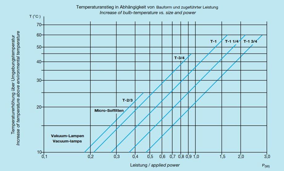
TEMPERATURE
The ambient working temperature affects the life of a lamp. Most of the radiation from an incandescent lamp is heat radiation resulting in a temperature increase during operation of between 10 and 55°C, depending on the lamp type. This temperature rise depends on the physical size of the lamp. Fig. 4 shows the relationship between temperature rise (for lamps between sizes T-⅔ to T-1¾) and power input. This chart applies to vacuum lamps only, constituting the larger part of our range.
If lamps are continuously operated at 125°C or more, out-gassing of the glass bulb will impair the vacuum. This entails an accelerated evaporation as well as an increased bulb temperature, with a simultaneous rise of current and a reduction of light input reducing life considerably.
THERMAL INFLUENCES (VACUUM- AND GAS FILLED LAMPS)
Normal operation of incandescent lamps results in blackening of the inner glass bulb wall caused by evaporation of the tungsten filament. In case of considerable evaporation of the filament, it can be assumed, that the filament cross section has been substantially reduced. This reduction is not uniform but localized, resulting in pronounced ‘notches’ mechanically weaker than the rest of the filament, leading to less resistance against shock or vibration. The cross section of the filament wire plays a decisive role in determination of lamp life. A lamp with lower voltage has a longer life at the same power dissipation than a higher voltage lamp having the same candle power.
Most MGG lamps are vacuum types. Several projection and point-light lamps are gas filled (inert gases), reducing the evaporation rate of the filament. In addition, a higher light output is obtained and the filament size can be reduced to give an almost point-light source. This is a great advantage for lens-ended lamps, whose optical qualities are important.
SHOCK AND VIBRATION
Some applications for incandescent lamps involve mechanical shock and vibration. When lamps are new or have been used for only a short time, the filament is relatively flexible. However, as filament ages, brittleness develops which can lead to fractures. This applies especially to lamps with higher voltages (long filaments) and lower current rating (thin wires). Those filaments are more prone to deformation which may lead to shorted terms and hence to premature lamp failure. So it is advisable to use lamps with lower voltages and higher current ratings in applications where shock and vibration may be encountered.
The support wires and filaments used in MGG lamps are subjected to special annealing procedures during manufacture, which produces a lamp with high mechanical stability and resistance to shock and vibration (see "Material"). By careful use of filament supports special lamps can be manufactured for use in delicate mechanical environments.
‘Pre-heating’ the lamp filament by applying between 10 and 15% of the rated voltage in ‘off’-state (see "Rated Resistance") will keep the filament more flexible and less brittle than it would be in the ‘cold’-state. This reduces the danger of breakage under shock or vibration.
VACUUM OR GAS
As already stated under "Life", we can supply certain lamps in a gas filled version. These types of lamps are usually for projection- and point-light applications. For indicator or signal lamps gas filled lamps are not recommended due to the higher bulb temperature caused by gas convection, having a detrimental effect in keyboards, switches, pushbuttons, indicators, displays etc. Plastic bezels, lenses and enclosures could be deformed as well as changed in color.
WIRE TERMINALS
The basic form of all lamps is a wire-ended version supplied as standard with a highly polished electro-tin coating (layer thickness 1.5µm min.) designed for easy soldering (acc. to MIL-T-10727 and DIN 40046). Gold plated and platinum coated leads are also available on demand.
BASES
The WT-lamps can be supplied with bases to international standards, e.g. European Norm (EN), US-MIL-Specification, Norme Française, DIN-Norm, BSI, IEC, ISO, ANSI etc. For some of these lamps, the filament position is carefully adjusted, and a light center length is specified (LCL). If required, special bases can be supplied acc. to specific customer requirements.
COLORING OR FROSTING
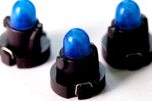
MGG lamp bulbs are made of clear glass. For many applications coloring is necessary. The following colors are available:
Red – Green – Yellow - Blue – Opal white – Orange – Blue-white
Under chapter "Material" we detailed order codes for colors. In addition to coloring the lamps can be supplied frosted, giving a diffused emission.
Another option could be the use of colored silicone caps (filters).
LENS-ENDED LAMPS
The light emitted by the filament is radiated in all directions, but the filament supports and bases influence the output light pattern. Many applications require a concentrated radiation of light in direction of the lamp axis. For these applications most MGG lamps can be supplied with a lens-ended bulb. Lens-ended lamps are normally supplied with voltages up to 6 Volt because no filament supports are necessary then - this might impair the light beam output. Higher voltages are available, at this stage up to a maximum of 36 Volt.
Lamps having tinned wire leads are mostly soldered. During preparation for soldering the lead should never be bent sharply near the seal, because of damage- danger to the vacuum seal or a mechanical breakage of the wire. During soldering care should be taken, that solder never touches the glass bulb, because this may cause leaks or microscopic flaws leading to early failure.
Wire-ended lamps should be fixed after soldering to avoid high mechanical shocks and high stress to the lamps. Suitable supports are distance pieces, plastic covers or certain adhesives. If adhesives are used, care should be taken to minimize the effect of differing coefficients of expansion of the materials used, to avoid mechanical stressing of the glass bulb, which may lead to lamp failure.
We can supply lamp holders for all these types. The base required for any lamp is referred to on the page where the lamp is shown in the catalog. For T-1 to T-1 ¾ lamps lamp extractors are also available. The use of a lamp extractor facilitates the change of a lamp, especially in positions difficult to access.
To make the most of the advantages of micro incandescent lamps, and to ensure that the average life is reached, the following precautions should be taken:
|
|
|
|
Usually it is just necessary to state the type number in inquiries or orders, e.g. MGG 1280-00. This gives a clear, unambiguous identification of the lamp. For the same lamp type, but with a sub-midget-base the order code would be 1280-04.
If you cannot find the lamps you require in the catalog, but need a special version, these can be supplied, but we would need the following information (we do not necessarily need every parameter specified below):
- Voltage
- Current (with tolerance)
- Mean spherical candle power or luminous flux (with tolerance)
- Life
- Type of lamp
- Wire terminals
- If based: base type (please specify)
- Mechanical dimensions
- Bulb shape (flat/round/lens-ended/globular)
In addition a drawing or sample of the required lamp would help considerably, as well as references to another manufacturer´s part number, norms or standards (see Technical Information- Introduction).
Subject to technical amendments.